December 02, 2014

CD Lamp with LEDs

Versión del blog en Español aquí

Throughout my life, I've been accumulating an important quantity of CDs and DVDs. Nowadays, with hard drives and pen drives all over the place, I barely use the round plastic things anymore. That's way I decided to get rid of all of them that I could find. It turns out I had a bunch and felt like a waste of money just to throw them away, so I decided to make a last useful thing with them. A LED-CD Lamp.
I'm not the first one to come up with this idea. I had seen many lamps over the internet, but I didn't want to get influenced for other people's designs, so I just started mine from scratch. (Any resemblance [except for the CDs, obviously] with other lamps is pure coincidence).
Again, my mistake is to get too excited with the project I'm working on, and I forget to make an exhaustive documentation of all the steps I took, but I'll do my best to explain things clearly with the few pictures I took.
I removed the old curtains of my apartment, and with them, the rods where they were hanging. Again, instead of just throwing them away, I decided to make something new with them, so I cut them in pieces of 50cm to give rigidity to the lamp structure.
Taking the dimensions of the rod into consideration, I designed the bottom and the top for my lamp.
Bottom part of the lamp
Top part of the lamp
The rod parts will go in the small holes surrounding the big hole for the CDs.
I did buy the RGB LED stripe, and cut two pieces of 50cm (the height of the lamp).
I say I cut two pieces because the whole stripe has a limitation in the angle it can bend without compromising the components, and I needed a 180º fold at the top of the lamp to be able to stick the two pieces of the stripe "back to back". I then soldered a small wire in every connection of one end of every stripe.
And now only was left to solder the cables of the same connection with each other. The +12V of one stripe with the +12V of the other stripe, blue with blue, red with red, and green with green. In the picture from above, I soldered a colored wire corresponding to the color of the connection, so it was just a matter of soldering the same colors together.
And finally, the set up was pretty easy:
  1. Place the bottom printed part on the table.
  2. Insert the rod pieces in the holes surrounding the CDs.
  3. Put the CDs in the center of the bottom part.
  4. Fit the two stripes through the CDs.
  5. Close the structure with the top printed part.
And this is the result:
And a short video:


January 15, 2014

Upgrading my Prusa i2

Versión del blog en Español aquí

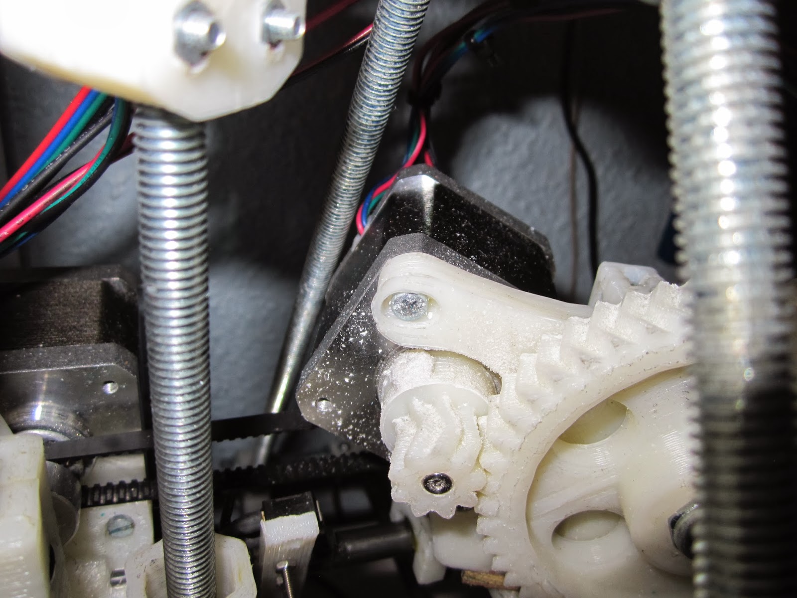
A short time ago, mu Prusa 2 had a setback where some of the parts broke in several pieces. Fortunately, I already knew this could happen and had an extra set of printed parts in case of something like this happened. I basically had to set up the printer from scratch, so I decided to make a good use of the opportunity and upgrade the printer to be able to use all the printing space. In the original design, the triangular frames are inside the Z motors, and it could happen that the X carriage with the extruder might collide with the frames. At the bottom of the printing space there's usually no problem because the bars are sufficiently separated from each other, but as the extruder goes up in the Z axis, the bars merge together, limiting the space in which the printer can move. This is why, instead of having a cubic printing space of 20x20x10 cm, what we have is a pyramidal printing space with a base of 20x20 cm and a height of 10 cm, and we don't want this. Here there are some examples of the motor colliding with one bar of the frame.


The solution was surprisingly easy. I just bought all the parallel bars to the X axis 50 cm in length, and this time I set up the motors for the Z axis inside the triangular frames. I also put two extra legs in the center of the structure to have more rigidity. This is the result:


 Obviously, by using longer bars, the size of the printer is increased, but the printing zone looks clearer and there's no risk of parts colliding with each other.

September 18, 2013

3D printing with my Raspberry Pi

Versión del blog en Español aquí

A few weeks ago, a couple of friends and I finally decided to build our own 3D printer. The printer we chose is the Prusa Iteration 2 and the parts we used are the ones that can be found  at Proyecto Clone Wars. Some parts are printable by another person with a 3D printer, and you can buy the others in a hardware store and other specialized stores. We bought them in RepRapWorld.

For the assembly we follow the fantastic guide that can be found in iearobotics (in Spanish).

And after putting some neon lights I had, this is the result:


The lights are useful to check the progress of the printing without having to turn on the light of the room.

Once I assembled the printer and I had choose how I was going to send the movement instructions. I could have used mi desktop but some of the printings last quite a long time, and I wanted to be able to turn off/restart the PC whenever I wanted without having to wait for the printing to finish. I also thought about using my laptop but then I wouldn't be able to take it anywhere, which is the purpose of a laptop.

That's why I decided to set up my Raspberry Pi to use it as the controller to send the movement instructions. I installed the Raspberry Wheezy distribution that can be found at the website of the platform. Tu use the printing interface you will need to install python in the system. I installed version 2.7. Now you have to install wxpython. To do this, open a terminal and type:

sudo apt-get install python-wxgtk2.8 python-wxtools wx2.8-i18n libwxgtk2.8-dev

Now serial for python must be installed. Download the package, extract it, get into the directory and execute:

sudo python setup.py install

Finally, download pronterface. This program will manage the printings. Just extract the files from the package, get into the directory and execute:

sudo python pronterface.py

It is important to execute the command as administrator because I had some problems when the interface tried to modify something and the terminal complained that it couldn't.

And that's all. My Raspberry Pi is managing the printings of my 3D printer.

NOTE: If you have a regular computer, I recommend to generate the G code from the pieces there, and then just transfer the files to the Raspberry Pi with a pendrive. Just to send the movement instructions, the platform works fine, but generating the G code requires quite an amount of computing and you can find yourself waiting for an hour just to generate the code of a small piece.

Now that I can print solids, I designed a box for the electronics with the controllers for the stepper motors. I used an old fan from a computer and a refrigerating base for a hard drive with two small fans to cool down the electronics. This is the result:


June 02, 2013

LED lamp medieval style

Versión del blog en Español aquí

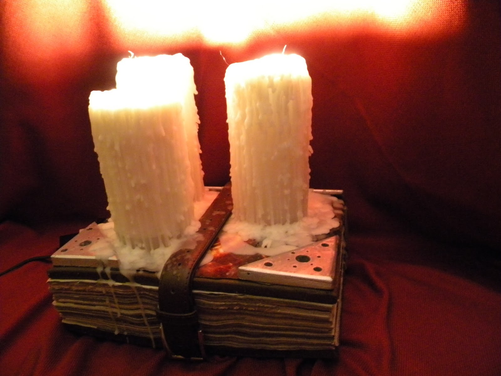
I always loved the medieval stuff and when I was playing Diablo III (unfortunately I don't have time anymore) I saw a video where one of the scenes happened in a library. There were many old books piled in stacks with big melted candles on top of them, and I really loved how medieval-looking image that was (or at least, that's what I thought). Since one of my many hobbies is to build things that I like, no matter how difficult or unrealistic the project is, I went for it, having in mind the idea from the video. As to be expected, using real candles can be dangerous and since I didn't feel like setting anything on fire, I chose to use LEDs.

I went to a lamp store and bought and LED lamp that came in parts. On the one hand you had the luminosity regulator and the tension converter, and on the other hand you had the LED lights. I was going to need three of them for my experiment, but I could have used up to six of them.

In a store that sells stuff for hobbies, I bought a round candle mold and lots of bee wax. You can also find paraffin wax, but I like the smell and the touch of the first one better.

And in a hardware store, I bought an aluminium pipe, of around two centimeters in diameter, and some paint in spray.

I would have liked to have pictures of all the process, but when I decided I was going to make the lamp, I didn't know I was going to end up writing a blog like this one, so I apologize in advance if the explanation seems a little poor, even though I will try to give all the details I can remember. But of course, don't hesitate to ask as many questions as you like.

Making the candles:
The candles had to be hollow in the middle so the wire of the lamp could go through them. I cut the pipe  in three different sizes that I wanted for the three candles. Then, I put every piece inside the mold, in the middle, so when I pour the wax the core would stay hollow.

You have to be specially careful while melting wax. That's why I strongly recommend to read the instructions before doing it and follow the steps thoroughly because handling the wax in an improper manner can cause very dangerous results.

Making the book:
For the cover, I used some scraps of wood I had at home and painted them with the sprays. For the pages of the book I used old newspapers that I cut with a guillotine and then glued together so they didn't move. I  glued a burnt photo to give it an old, used look and smaller pieces of wood painted with silver paint. I then made three holes where the candles would go so the cables of the LEDs could be put through.

Putting everything together:
When the wax cools down, it shrinks, so even when you filled the mold all the length of the central pipe, you'll see that a couple of centimeters of the pipe protrude. This is good, because it will be the end that will fit in the holes of the book and will give the candles more stability.

We fit the candles in the holes of the book and put the cables of the LEDs through them. Since the cases of the lights were in sight, one way to cover them was to melt wax over them. This makes it look that the candles have been used and the melting wax spilled over.

The last step was to tie a belt around the book and connect the LED's to the converter.

This was the final result:


April 12, 2013

jaBOTron


Versión del blog en Español aquí

This year, I went with a couple of friends to Alcabot 2013 and participated in three of the competitions:  tracking, sprinter and minisumo, as part of the GoShield team.

Out of the three robots, I assembled and programmed the tracking robot, always with my team's help and support, and I named it jaBOTron.

I based the design of the robot on my old Lady-Bot and used the following components:
I had some problems with the code in the first round and the robot didn't work as good as I was expecting, but in the previous hour to the final rounds, I got time to debug my code a little more and, in the end, the robot showed and incredible improvement in comparison to the first round.

I got seventh out of thirteenth in this category, but keeping in mind that I only had two weeks to assemble and program the robot, the result was very positive. Also, the experience has been really good and the most important thing, I learned a lot and I'll be back next year with new ideas.

I will update this post with the videos of the competition as soon as the organization publishes them.

March 02, 2013

Lego case for my Raspberry Pi v2.0


Versión del blog en Español aquí

After building the first case for my Raspberry Pi with Lego pieces, and thanks to some advice from some of my friends, I decided that my first case needed some (if not many) improvements.

For the second version, I took my time and found pieces of the same color, in this case, red. I chose this color because I wanted to put some holes for ventilation and the only pieces I had where red. I also put small doors for the RCA video connector and the audio jack so that I can access them easily. I also put a couple of hinges on the cover so I can have easy access to the inside. And finally, my idea is to overclock the board and to do this I need to use heat-sinks on the chips, I placed a small fan to help with the circulation of air.

This is the result:

UPDATE: A short time ago, a reader made me notice that I mention heat sinks for my Raspberry Pi in this entry, but that I don't post any pictures. Well, with my most sincere apologies for this slip and the delay, here there is a couple of pictures of the board with the heat sinks:

Determining where the heat sinks should go was easy thanks to this great article (in Spanish, easy to understand just by watching the pictures).

March 01, 2013

Lego case for my Raspberry Pi


Versión del blog en Español aquí.

I won a Raspberry Pi at the competition. I needed a case and since the student's life is really poor, I used my old Lego pieces to make one. I apologize in advance for the poor quality of my pictures but the camera in my cellphone is really bad.
You can see in the picture above that the place where the Raspberry Pi stands has small pieces. This is so the circuits don't touch the bottom. When I was assembling the structure, I thought I was going to have to use a tool to modify some pieces for the board to fit inside, but it turned out the Lego pieces had the precise size and everything fits perfectly.
For the cover I used other pieces so they hold the Raspberry Pi still once everything is in place. The next couple of pictures show the case finished. 
The following picture shows the Ethernet and USB connections. 
HDMI connector.
And the SD memory card and the hole for the power supply pin.
The other connections are covered by the pieces, but if I ever need to use them, I just have to remove some of the pieces and open a hole. Really easy.

As it can be seen, all the pieces have a weird discoloration. This is because they're really old, but I couldn't be happier with the result.